Trong bài viết tuần trước, chúng ta đã cùng nhau khảo sát việc thiết lập Etherchannel giữa hai router Cisco. Trong bài viết tuần này, chúng ta cùng nhau tiếp tục khảo sát việc thiết lập Etherchannel giữa một router và một switch.
Sơ đồ
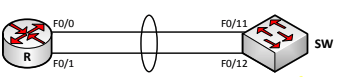
Mô tả
- Bài lab này thực hiện cấu hình Etherchannel giữa một router và một switch. ∙ Router trong bài lab này là một router Cisco 2811 với hệ điều hành được sử dụng là “c2800nm-adventerprisek9-mz.124-24.T3.bin”.
- Switch trong bài lab này là một switch Cisco 3560 với hệ điều hành được sử dụng là “c3560-ipservicesk9-mz.122-55.SE4.bin”.
Thực hiện
Bước 1: Cấu hình Etherchannel trên router
- Cấu hình một Etherchannel trên router R mang số hiệu là Po1 bao gồm hai cổng thành phần là F0/0 và F0/1.
- Đặt địa chỉ trên cổng Po1 là 192.168.1.1/24.
Cấu hình
R(config)#interface po 1
R(config-if)#ip address 192.168.1.1 255.255.255.0
R(config-if)#exit
R(config)#interface range f0/0 - 1
R(config-if-range)#no shutdown
R(config-if-range)#channel-group 1
%Interface MTU set to channel-group MTU 1500.
FastEthernet0/0 added as member-1 to port-channel1
%Interface MTU set to channel-group MTU 1500.
%Interface MTU set to channel-group MTU 1500.
FastEthernet0/1 added as member-2 to port-channel1
%Interface MTU set to channel-group MTU 1500.
R(config-if-range)#exit
Kiểm tra
Ta kiểm tra rằng các cổng đều đã up/up:
R#show ip interface brief
Interface IP-Address OK? Method Status Protocol FastEthernet0/0 unassigned YES unset up up  FastEthernet0/1 unassigned YES unset up up  Serial0/0/0 unassigned YES unset administratively down down  Serial0/1/0 unassigned YES unset administratively down down  Port-channel1 192.168.1.1 YES manual up up
Ta cũng kiểm tra các thông số của cổng Po1:
R#show interfaces po 1
Port-channel1 is up, line protocol is up
 Hardware is FEChannel, address is 0021.a07d.2480 (bia 0021.a07d.2480)  Internet address is 192.168.1.1/24
 MTU 1500 bytes, BW 200000 Kbit/sec, DLY 100 usec,
 reliability 255/255, txload 1/255, rxload 1/255
 Encapsulation ARPA, loopback not set
 Keepalive set (10 sec)
 ARP type: ARPA, ARP Timeout 04:00:00
 No. of active members in this channel: 2
 Member 0 : FastEthernet0/0 , Full-duplex, 100Mb/s
 Member 1 : FastEthernet0/1 , Full-duplex, 100Mb/s
 No. of Non-active members in this channel: 0
 No. of PF_JUMBO supported members in this channel : 0
 Last input 00:00:00, output never, output hang never
 Last clearing of "show interface" counters never
 Input queue: 0/150/0/0 (size/max/drops/flushes); Total output drops: 0  Queueing strategy: fifo
 Output queue: 0/80 (size/max)
 5 minute input rate 4000 bits/sec, 1 packets/sec
 5 minute output rate 0 bits/sec, 0 packets/sec
 294 packets input, 133532 bytes
 Received 310 broadcasts, 0 runts, 0 giants, 0 throttles
 0 input errors, 0 CRC, 0 frame, 0 overrun, 0 ignored
 0 watchdog
 0 input packets with dribble condition detected
 3 packets output, 197 bytes, 0 underruns
 0 output errors, 0 collisions, 0 interface resets
 16 unknown protocol drops
 0 babbles, 0 late collision, 0 deferred
 0 lost carrier, 0 no carrier
 0 output buffer failures, 0 output buffers swapped out
Như vậy, ta đã thiết lập xong Etherchannel trên router.
Bước 2: Cấu hình Etherchannel layer 3 trên switch
- Cấu hình Etherchannel mang số hiệu Po1 trên switch gồm hai cổng thành phần F0/11 và F0/12.
- Đặt địa chỉ IP 192.168.1.2/24 trên cổng Po1.
- Kiểm tra rằng router và switch đã ping được nhau sử dụng hai địa chỉ IP đã cấu hình.
Cấu hình
SW(config)#interface range f0/11 - 12
SW(config-if-range)#no switchport
SW(config-if-range)#channel-group 1 mode on
Creating a port-channel interface Port-channel 1
SW(config-if-range)#exit
SW(config)#interface po 1
SW(config-if)#ip address 192.168.1.2 255.255.255.0
SW(config-if)#exit
Ghi chú
Việc cấu hình Etherchannel phía switch được tiến hành như bình thường. Một điểm cần lưu ý là khi thực hiện Etherchannel với router, ta cần phải sử dụng mode “ON”, không sử dụng các mode thương lượng tự động PAgP hoặc LACP vì phía router chỉ hỗ trợ mode “ON” (xét trong ngữ cảnh của bài lab này khi router 2811 với IOS đang sử dụng chỉ hỗ trợ mode “ON”).
Kiểm tra
Ta kiểm tra trên switch rằng Etherchannel đã được thiết lập:
SW#show etherchannel summary
Flags: D - down P - bundled in port-channel
 I - stand-alone s - suspended
 H - Hot-standby (LACP only)
 R - Layer3 S - Layer2
 U - in use f - failed to allocate aggregator
 M - not in use, minimum links not met
 u - unsuitable for bundling
 w - waiting to be aggregated
 d - default port
Number of channel-groups in use: 1
Number of aggregators: 1
Group Port-channel Protocol Ports
------+-------------+-----------+---------------------------------------------- 1 Po1(RU) - Fa0/11(P) Fa0/12(P)
Ta thực hiện ping kiểm tra giữa router và switch:
R#ping 192.168.1.2
Type escape sequence to abort.
Sending 5, 100-byte ICMP Echos to 192.168.1.2, timeout is 2 seconds: ..!!!
Success rate is 60 percent (3/5), round-trip min/avg/max = 1/2/4 ms

R#ping 192.168.1.2
Type escape sequence to abort.
Sending 5, 100-byte ICMP Echos to 192.168.1.2, timeout is 2 seconds: !!!!!
Success rate is 100 percent (5/5), round-trip min/avg/max = 1/2/4 ms
Bước 3: Cấu hình Etherchannel layer 2 mode access trên switch
Hiệu chỉnh lại cấu hình Etherchannel đã thực hiện với switch ở bước trên để cổng Etherchannel của switch bây giờ là một cổng layer 2 hoạt động ở mode access. ∙ Đặt lại IP 192.168.1.2/24 cho interface vlan 1 của switch. Kiểm tra rằng địa chỉ này và địa chỉ trên cổng Etherchannel của router đi đến được nhau.
Cấu hình
Gỡ bỏ cấu hình Etherchannel đã thực hiện ở bước 2:
SW(config)#default interface f0/11
Interface FastEthernet0/11 set to default configuration
SW(config)#default interface f0/12
Interface FastEthernet0/12 set to default configuration
SW(config)#no interface po1
Thực hiện cấu hình Etherchannel layer 2 với các cổng thành phần là F0/11 và F0/12:
SW(config)#interface range f0/11 - 12
SW(config-if-range)#switchport mode access
SW(config-if-range)#channel-group 1 mode on
Creating a port-channel interface Port-channel 1
SW(config-if-range)#exit
Đặt IP trên interface vlan 1 của SW:
SW(config)#interface vlan 1
SW(config-if)#no shutdown
SW(config-if)#ip address 192.168.1.2 255.255.255.0
SW(config-if)#exit
Kiểm tra
Ta kiểm tra rằng Etherchannel layer 2 đã được thiết lập trên switch:
SW#show etherchannel summary
(Đã lược bớt một số dòng cho gọn kết quả show)
Group Port-channel Protocol Ports
------+-------------+-----------+----------------------------------------------
 1 Po1(SU) - Fa0/11(P) Fa0/12(P)
Cổng Po1 hiện đang thuộc VLAN 1:
SW#show vlan brief
VLAN Name Status Ports
---- -------------------------------- --------- -------------------------------
1 default active Fa0/1, Fa0/2, Fa0/3, Fa0/4
Fa0/5, Fa0/6, Fa0/7, Fa0/8
Fa0/9, Fa0/10, Fa0/13, Fa0/14
Fa0/15, Fa0/22, Fa0/23, Fa0/24

Gi0/1, Gi0/2, Po1
1002 fddi-default act/unsup
1003 token-ring-default act/unsup
1004 fddinet-default act/unsup
1005 trnet-default act/unsup
Ta kiểm tra rằng router đã ping được địa chỉ trên interface vlan 1 của switch:
R#ping 192.168.1.2
Type escape sequence to abort.
Sending 5, 100-byte ICMP Echos to 192.168.1.2, timeout is 2 seconds: .!!!!
Success rate is 80 percent (4/5), round-trip min/avg/max = 1/3/4 ms
Bước 4: Etherchannel hoạt động như cổng trunk
- Cấu hình Etherchannel giữa R và SW thành đường trunk dot1Q.
- Cấu hình router định tuyến VLAN cho 3 VLAN 1, 2 và 3. Sử dụng các địa chỉ 192.168.2.1/24 và 192.168.3.1/24 trên các cổng sub – interface nối đến các VLAN 2 và 3.
- Trên switch tạo thêm các VLAN 2 và 3. Thực hiện đặt các địa chỉ 192.168.2.2/24, 192.168.3.2/24 cho các interface vlan 2 và 3.
- Kiểm tra rằng các IP cùng subnet giữa router và switch đã thấy nhau. Cấu hình
Trên router R:
R(config)#interface po1.2
R(config-subif)#encapsulation dot1Q 2
R(config-subif)#ip address 192.168.2.1 255.255.255.0
R(config-subif)#exit
R(config)#interface po1.3
R(config-subif)#encapsulation dot1Q 3
R(config-subif)#ip address 192.168.3.1 255.255.255.0
R(config-subif)#exit
Trên switch SW:
SW(config)#interface po 1
SW(config-if)#switchport trunk encapsulation dot1q
SW(config-if)#switchport mode trunk
SW(config-if)#exit
SW(config)#vlan 2
SW(config-vlan)#exit
SW(config)#vlan 3
SW(config-vlan)#exit
SW(config)#interface vlan 2
SW(config-if)#no shutdown
SW(config-if)#ip address 192.168.2.2 255.255.255.0
SW(config-if)#exit
SW(config)#interface vlan 3
SW(config-if)#no shutdown
SW(config-if)#ip address 192.168.3.2 255.255.255.0
SW(config-if)#exit
Kiểm tra
Ta kiểm tra rằng các địa chỉ kết nối trực tiếp đã ping được nhau:
R#ping 192.168.1.2
Type escape sequence to abort.
Sending 5, 100-byte ICMP Echos to 192.168.1.2, timeout is 2 seconds: !!!!!
Success rate is 100 percent (5/5), round-trip min/avg/max = 1/2/4 ms
R#ping 192.168.2.2
Type escape sequence to abort.
Sending 5, 100-byte ICMP Echos to 192.168.2.2, timeout is 2 seconds: ..!!!
Success rate is 60 percent (3/5), round-trip min/avg/max = 1/2/4 ms
R#ping 192.168.3.2
Type escape sequence to abort.
Sending 5, 100-byte ICMP Echos to 192.168.3.2, timeout is 2 seconds: ..!!!
Success rate is 60 percent (3/5), round-trip min/avg/max = 1/2/4 ms
Kết luận
Ta có thể bó các cổng router thành một cổng Etherchannel và dùng cổng channel này đấu nối đến một cổng channel của switch. Cổng channel của switch có thể được sử dụng như một cổng layer 3 hoặc layer 2 và router thực hiện các cấu hình đấu nối trên channel giống như sử dụng một cổng vật lý bình thường đấu nối đến switch.
Cảm ơn các bạn!
Hẹn gặp lại các bạn trong các bài viết tiếp theo!